In last week’s blog, we followed a typical service provider through the early stages of SR deployment. While this blog did not reflect the actual deployment experiences of a real service provider, it did reflect issues that a real service provider faces as it plans for SR deployment. In this week’s blog, we will continue to address those issues as we continue to follow our typical service provider through the stages of SR deployment.
Initially, the service provider operated the IPv4 network depicted below.
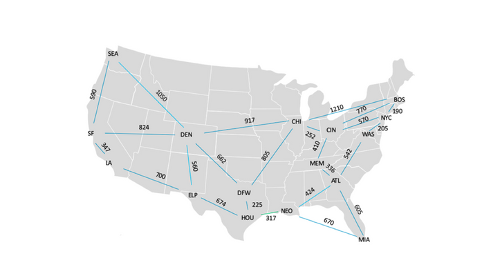
When the service provider deployed Ethernet Virtual Private Networking (EVPN), it also deployed SR paths to encapsulate EVPN traffic. Each SR path contained exactly one prefix segment and followed the least cost path from the SR ingress node to the SR egress node.
Because each SR path contained exactly one prefix segment and because prefix segments are relatively resistant to failure, path failure was not a significant issue. So long as the SR egress node was reachable from the SR ingress node, the SR path between them remained operational.
Soon thereafter, a customer in ATL originated three large flows, destined for WAS, NYC and BOS. These flows caused Link ATL->WAS to become overutilized. In order to divert traffic from that link, the service provider deployed a traffic engineered path from ATL to BOS, traversing MEM and CIN. The traffic engineered path contained the following segments:
- An adjacency segment traversing Link ATL->MEM
- An adjacency segment traversing Link MEM->CIN
- A prefix segment traversing the least cost path from CIN to BOS
While this SR path satisfies TE requirements, it is not entirely resistant to failure. It fails if Link ATL->MEM or Link MEM->CIN fail. It also fails if BOS becomes unreachable from CIN.
If the SR path fails, traffic sent through it is lost (i.e., blackholed). Therefore, SR path restoration mechanisms are required. In this blog, we will consider head-end restoration and Topology Independent – Loop Free Alternate (TI- LFA).
Head-End Restoration
Head-end restoration leverages a redundant path strategy to increase network reliability. Two paths are configured to provide connectivity from the SR ingress node to the SR egress node. One path provides primary connectivity while the other provides backup (i.e., secondary) connectivity. The SR ingress node forwards traffic through the primary path whenever it is available. When the SR ingress node detects primary path failure, it diverts traffic to the secondary path. When the primary path becomes operational again, the SR ingress node sets a timer. When that timer expires, the SR ingress node restores traffic to the primary path.
Following this strategy, the service provider configures a primary path from ATL to BOS as described above (i.e., through MEM and CIN). The service provider also configures Seamless Bidirectional Forwarding Detection (S-BFD) on the primary path. S-BFD verifies primary path continuity by sending probe messages from the SR ingress node to the SR egress node and waiting for responses. In this network, S-BFD can detect primary path continuity loss within 150 milliseconds of a network event. However, S-BFD reports primary path failure only if continuity is lost for 200 milliseconds or longer. This 200ms delay dampens the effect of transient network events. It is important to note that S-BFD can take 350ms or more to report a link failure, resulting in packets being dropped.
Finally, the service provider configures a secondary path that contains the following segments:
- The prefix segment from ATL to DFW
- The prefix segment from DFW to CHI
- The prefix segment from CHI to BOS
The service provider chooses this path for the following reasons:
- Because it satisfies TE requirements (i.e., it is unlikely to traverse Link ATL->WAS)
- Because it’s segment-diverse from the primary path
The primary and secondary paths are segment-diverse from one another because they do not contain any common segments or segment endpoints. If they contained a common segment or segment endpoint, failure of that segment or segment endpoint would cause both paths to fail.
In this network, links do not share physical resources (i.e., fiber, conduit) with one another. Therefore, segment-diversity guarantees physical diversity.
Head-end restoration procedures are invoked whenever S-BFD reports primary path failure (i.e., persistent loss of continuity). Persistent loss of continuity can be caused by any of the following network events:
- Persistent failure of the adjacency segment that traverses ATL->MEM
- Persistent failure of the adjacency segment that traverses MEM->CIN
- Persistent failure of the segment endpoint in BOS
Head-end restoration procedures are not invoked when S-BFD detects a transient loss of connectivity. For example, if the S-BFD damping timer is set to 200 milliseconds and S-BFD detects a loss of continuity that persists for only 100 milliseconds, S-BFD will not report a loss of continuity and head-end restoration will not be invoked.
This may happen when a link along the prefix segment that connects CIN to BOS fails. When Links CIN->NYC and NYC->BOS are both operational, the least cost path from CIN to BOS traverses those links. However, if either of those links fails, a transient loss of connectivity occurs. Unmitigated, this transient loss of connectivity would persist until the Interdomain Gateway Protocol (IGP) converges and shifts traffic to the new least cost path (i.e. via Link CIN->BOS). The service provider can deploy Link Free Alternate (LFA) routes to mitigate the effects of this link failure.
Conclusion
In our last two blogs, we followed a typical service provider through the early stages of SR deployment. In this blog we introduced Traffic Engineering (TE) and head-end restoration. Next week, we will introduce LFA route solutions.
On June 10 (US/EMEA) and June 11 (APAC), get a deep dive into automated next-generation data center operations in interactive breakout sessions at our Juniper Virtual Summit for Cloud & Service Providers. Register here.


