In previous blogs, we introduced Segment Routing (SR) paths, segments, and label stacks. Now that we are familiar with SR fundamentals, we can discuss the most common SR application, Traffic Engineering (TE).
TE is a discipline that assigns traffic flows to network paths in order to satisfy Service Level Agreements (SLAs). For example, assume that a service provider maintains an SLA with a customer. The SLA guarantees low loss but does not guarantee low latency. Therefore, the service provider might apply a TE policy to that customer’s traffic, which forces it to take low loss paths. Since the SLA doesn’t specify the latency required, the traffic may flow on either low or high latency paths to its destination.

The Starting Point
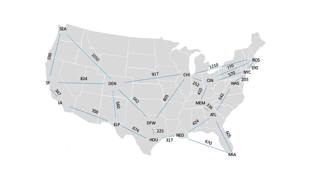
In order to understand SR-TE, we will follow a typical service provider through the stages of its SR deployment. Initially, the service provider operates the IPv4 network depicted above. In this network, the most significant factor influencing latency is propagation delay (i.e., circuit mileage). So, in order to optimize for latency, the service provider configures Interior Gateway Protocol (IGP) metrics to reflect circuit mileage and allows traffic to follow the IGP least cost path.
The network is designed so that multiple paths connect any two nodes. The IGP cost associated with any path is equal to the sum of the metrics associated with its links along the path. For example, the least cost path from ATL to NYC traverses Link ATL->WAS (metric 542) and Link WAS->NYC (metric 205). So, the cost associated with that path is 747 (i.e., the sum of 542 and 205).
The next best path from ATL to NYC traverses Link ATL->MEM (metric 336), Link MEM->CIN (metric 410) and Link CIN->NYC (metric 570). So, the cost associated with that path is 1,316 (i.e., the sum of 336, 410 and 570).
Tunneling With SR
Motivated by customer demand, the service provider deploys multitenant data centers at each of its points of presence. It also offers Ethernet Virtual Private Network (EVPN) connectivity among the data centers. In order to support EVPN, the service provider must encapsulate customer (i.e., Ethernet) traffic for transport across the IPv4 backbone. Because network utilization is moderate, customer flows can continue to follow the IGP least cost path.
Now, the service provider must choose among the following encapsulation techniques:
The service provider anticipates a time when the network will become heavily loaded and, in order to satisfy SLA’s, some traffic will need to be diverted from the IGP least cost path. Because neither VXLAN nor LDP-signaled MPLS offer TE capabilities, the service provider chooses SR-MPLS.
The service provider enables SR-MPLS and configures a prefix segment endpoint on each node. This causes every node to create a prefix segment to every other node. Thus, when an EVPN Provider Edge (PE) router receives an Ethernet frame from a data center tenant, it encapsulates the frame in an MPLS label stack. The outermost entry of the MPLS label stack represents a prefix segment and causes the packet to be forwarded along the least cost path to the egress PE.
Managing A Few Large Flows
Soon the data centers become successful and the demand for bandwidth grows quickly, faster than the rate at which new circuits can be installed. As links become overutilized, the service provider diverts latency-tolerant traffic away from them in order to prevent packet loss. As new circuits are installed, traffic is returned to the least cost (i.e., latency optimized) path.
For example, when a customer in ATL originates three large, latency-tolerant flows, destined for WAS, NYC and BOS, the Link ATL->WAS becomes overutilized.
The service provider must divert some traffic away from Link ATL->WAS. However, the service provider must not divert so much traffic that other links become overutilized. Therefore, the service provider decides to steer the flow from ATL to BOS through Links ATL->MEM, MEM->CIN, CIN->NYC and NYC->BOS, while leaving the flows from ATL to WAS and ATL to NYC on the least cost path.
In order to steer packets belonging to the flow, the service provider implements an SR policy on the SR ingress node in ATL. The SR traffic-steering policies identify the packets belonging to the flow and prepend an MPLS label stack to each packet. Each member of the MPLS label stack represents a segment that the packet must traverse.
Now, the service provider must decide which of the following SR paths is most desirable for this flow:
1. Traverse the prefix segment that connects ATL to CIN, followed by the prefix segment that connects CIN to BOS.
2. Traverse the adjacency segments ATL->MEM, MEM->CIN, CIN->NYC and NYC->BOS, in that order.
3. Traverse the adjacency segments ATL->MEM, and MEM->CIN, in that order. Then traverse the prefix segment that connects CIN to BOS.
In order to identify the most desirable SR path, the service provider must consider the following factors:
- MPLS label stack size
- Resilience
- Behavior during link and node failures
The MPLS label stack size is determined by the number of segments in the SR path. Because none of the above-mentioned SR paths contain more than four segments, MPLS label stack size is not a significant factor when choosing among them.
Resilience is determined by the type and number of segments in the SR path. In previous blogs, we explained that an SR path is operational if all its segments are operational. We also explained that a prefix segment is operational if its egress is reachable from its ingress, over any path. By contrast, an adjacency segment is operational if its egress is reachable from its ingress, over a specified path.
Therefore, the first SR path, mentioned above, is most resilient. It contains only two prefix segments, terminating in CIN and BOS. So long as CIN is reachable from ATL, over any path, the first segment remains operational. Likewise, so long as BOS is reachable from CIN, over any path, the second segment remains operational. No single link failure can cause the first SR path to fail.
By contrast, the second SR path, mentioned above, is least resilient. It contains four adjacency segments. If any of the links associated with those segments fails, the SR path fails.
While the first SR path, mentioned above, is most resilient, it exhibits a highly undesirable behavior during some link failures. If either Link ATL->MEM or MEM->CIN fail, the SR path reroutes as follows:
- The segment terminating at CIN traverses Links ATL->WAS, WAS->NYC, and NYC->CIN
- The segment terminating at BOS traverses Links CIN->NYC, and NYC->BOS
Because the SR path returns to Link ATL->WAS, that link returns to its overutilized state. Furthermore, path latency increases due to a needless round trip between NYC and CIN.
So, the service provider chooses the third SR path, mentioned above. While it is not as resilient as the first option, it does not exhibit undesirable behaviors during node and link failures. However, it is more resilient than the second, because it does not fail if Links CIN->NYC or NYC->BOS fail.
If the above sounds quite labor-intensive, using an SDN Controller, such as Juniper’s NorthStar Controller offers an alternative approach. NorthStar computes and instantiates the SR-TE paths and automatically changes them as needed according to current traffic conditions, as detected via streaming telemetry.
Conclusion
In this week’s blog, we explored the use of Traffic Engineering in Segment Routed networks. SR-TE provides flexibility through its support of adjacency and prefix segments. However, each has its own strengths and weaknesses, so one must carefully consider which segment type to use. Adjacency segments are good at managing and maintaining pre-defined, deterministic traffic flows, forcing traffic that meets a defined policy to take a specific path through the network. However, adjacency segments are not the most resilient. If a given link or node along the path fails, the traffic won’t be able to reach its destination. Prefix segments provide greater resiliency and flexibility to real-time changes in the network. However, they can extend network paths, which adds latency to the end-to-end traffic flow.
Through a basic example, we explored how a network operator might use one of these two segment types, or a combination of them, to configure SR paths through their network. In the first option, all of the SR paths contained a single prefix segment and as a result, path failure was not a significant issue, but we found that link and node failures could alter our traffic’s path in ways that might introduce unwanted latency. We ruled out the second option due to its lack of resiliency. In the third option, an SR path containing two adjacency segments and one prefix segment was deployed. By using a combination of prefix and adjacency segments we were able to make the traffic flows a bit more deterministic, but reduced the overall resiliency of the path.
In next week’s blog, we will build on the lessons learned here and focus on SR path backup and restoration.
Learn how to build a modern network for the new era on June 10 (US/EMEA) and June 11 (APAC) at our Juniper Virtual Summit for Cloud & Service Providers.


