Load balancing techniques are crucial in AI/ML 400G/800G data center fabrics for optimal resource utilization and avoiding different forms of congestion. The characteristics of AI workloads in the training domain are different from traditional DC applications. For example, we can have a single fat flow (or “elephant flow”) that lives for a long time and constantly synchronizes the data chunks with many GPU-enabled servers, forming “n to 1” or “1 to n” communications. This requires more intelligent load balancing decisions inside the lossless AI Ethernet fabric—instead of just local node link bandwidth utilization and queue depth quality, the ASIC load balancing algorithm assesses an end-to-end path quality.
Global load balancing (GLB) is a new feature which is part of the 23.4R2 Junos Evolved software release on Tomahawk 5 chip-based QFX5240-OD and QFX5240-QD—64 x 800GbE Ethernet/IP platforms. GLB enhances the load balancing capabilities by adding an end-to-end path quality to the algorithm.
Elephant flows in the AI data center fabric
AI/ML fabrics have multiple ECMP links from leaf to spine to deliver ultra-high performance to GPU-enabled clusters—high bandwidth, low latency, efficient job completion time (JCT), and low tail latency offered to the AI workloads.
The traffic flows from the cluster servers are hashed at the top of the rack switch level onto different outgoing links for load-balancing purposes. When the entropies of the flows are insufficient, or there are elephant flows, traditional 5-tuple hashing might not be able to ensure good load distributions over all ECMP links, leading to congestion on certain links and under-utilization on other 400G/800G Ethernet links. Dynamic load balancing (DLB) is designed to avoid congested links and mitigate local congestion.
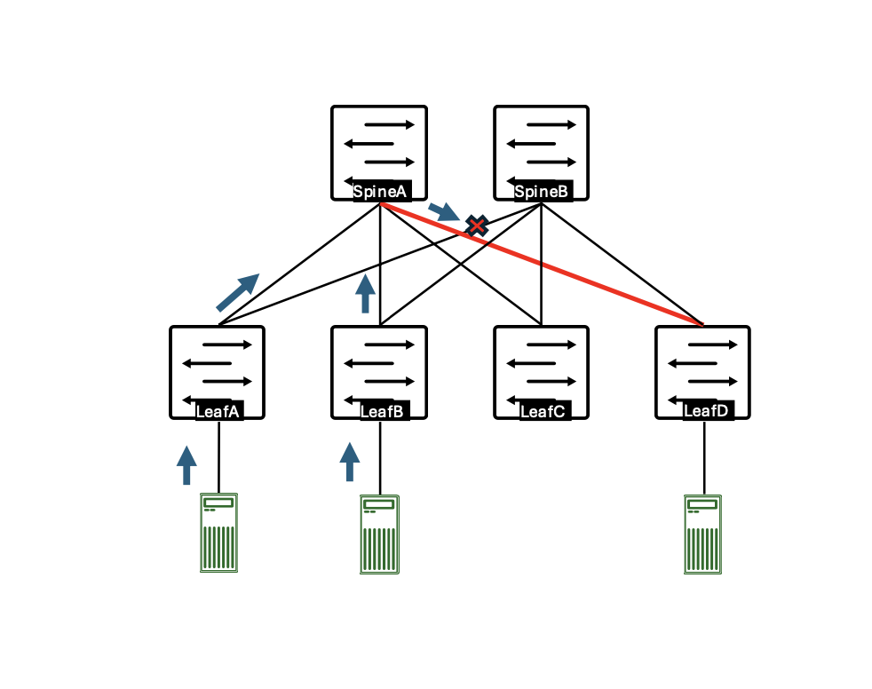
Figure 1: Leaf-spine topology where the congestion occurs at the spine level
Figure 1 illustrates the in-cast congestion at spine. Congestion may happen on a link from the spine to the egress leaf, so the ingress leaf node is unaware of the congestion at the spine level. The congestion, once it occurs from the spine to the egress leaf, can be signalized using the DCQCN ECN and PFC-DSCP, but this leads to reduced performance, especially when the congestion is persistent. That’s why relying on the ingress leaf is more efficient in offloading traffic to other spines to mitigate the congestion on the spine-to-egress leaf link. Currently, there is no mechanism to handle this scenario using legacy load balancing technologies.
How global load balancing works
GLB extends DLB by modulating the local path selection using path quality perceived at downstream switches. GLB allows an upstream switch to avoid downstream congestion hotspots and select a better end-to-end path. The GLB app from Broadcom reads the topology information from BGP next-hop and next-to-next-hop-node topology information advertisements.
GLB has two parts:
Part 1: A BGP control-plane part to learn the topology information—in Juniper’s implementation this is done using the BGP next-to-next-hop-node new attribute.
Part 2: Heartbeats with the path quality information is sent at the ASIC level.
For the control plane part, GLB uses the new BGP next-to-next-hop nodes (NNHN) capability in the next-hop dependent capabilities attribute to signal all next-next-hop-nodes of a given next-hop.

Figure 2 – NNHN Capability TLV Format of the BGP update
In the BGP capability information, we can find:
Next-hop BGP ID:
32-bit BGP identifier of the next-hop-node attaching this NHC capability.
Next-next-hop BGP IDs:
One or more 32-bit BGP identifiers, each representing a next-to-next-hop-node used by the next-hop-node for ECMP forwarding for the NLRI in the BGP update.
This IETF draft is used to implement the control-plane part of the GLB, which correlates the topology information with the heartbeat node information at the packet forwarding engine (PFE) level.
The second part related to the GLB heartbeats is sent by the PFE and will only be sent at the interfaces on which the BGP underlay peering is enabled between leaf and spine devices. This way, the GLB gets enabled only where it’s needed and does not consider the heartbeat information coming through the links that are not part of the leaf-spine fabric topology. Each unique next-to-next-hop-node will generate a simple path quality profile for the Tomahawk 5 GLB app. All next-hops sharing the same next-next-hop-node will be grouped together to form a GLB path. Two or more simple path quality profiles may be grouped into a compound path quality profile. If a route only has one next-to-next-hop node (as in the 3-stage Clos), it will be programmed with a profile ID corresponding to a simple path quality profile. A route with more than one next-to-next-hop-nodes (like in the 5-stage Clos) will be programmed with a profile ID corresponding to a compound path quality profile.
Based on the path quality profile and the corresponding paths of a route, The GLP app will know the next-to-next-hops of each next-hop leg. This will allow the app to use the combined link quality of the next-hop and next-to-next-hops to make load balancing decisions.When an EBGP session comes up, BGP sends a path monitor message to PFE, requesting the GLB app to start monitoring the quality of the link which the EBGP session is on. The GLB app will flood the link quality to neighboring routers so that it can use the link quality for GLB purposes.
The frequency of the heartbeat is change-based and a periodic 20ms.
From the packet forwarding decision perspective, once the path quality tables are created, the packets of the new flows will be directed to the paths with the best quality. When the calculated quality of the paths is the same, the path selection will follow the hash-based forwarding for the flowlet mode.
Configuring global load balancing
Below are the configuration options added as part of this feature:
 Currently, the “global-load-balancing” knob can be configured in two modes:
- “global-load-balancing helper-only”: BGP sends NNHN capability for the route it advertises. BGP instructs the GLB app to monitor the link qualities of all local links with EBGP sessions and flood them to all direct neighbors. The GPB app does not process link qualities from neighboring nodes and does not perform GLB. This is usually configured on 3-stage Clos spines.
- “global-load-balancing load-balancer-only”: BGP does not send NNHN capability for the route it advertises. BGP does not instruct the GLB app to monitor the link qualities of local links either. The app only receives link qualities from neighboring nodes and uses the combined link quality of next-hops and next-to-next-hops to make load balancing decisions. This is usually configured on the leaves.
Design options with global load balancing
Option 1: Single pod
Build one 3-stage Clos fabric with all QFX5240 switches and enable GLB on all nodes. Spine nodes will be in helper mode and leaf will be in load-balancer mode. Each QFX5240 leaf will connect 32x800gbps towards server and 32x800gbps towards spine. 64xQFX5240 leaf means 64x32x800gbps interfaces towards server, so one GLB domain can connect 2048x800gbps link towards server or 4096x400gbps link towards server. For example, one GLB domain can connect 4096 Nvidia H100 GPUs with end-to-end GLB. Hence, this topology will be good for enterprises deploying small-to-medium size clusters.

Figure 3
Ideally all spines and leaves should be GLB capable but not a mandatory requirement. Even if some of thespines or leaves are not running GLB (when the switches are not Tomahawk 5), GLB can still be used in the fabric on the nodes supporting it. The switches which are capable of GLB can continue to get the benefit of GLB while others are more susceptible to congestion.
Option 2: Multiple pods
GLB benefits the pods as described in option 1. However, GLB does not run between spine and super spine. Hence, there is no end-to-end GLB for inter-pod traffic. There is the chance of congestion on the super spine. As GLB is not running on the super spine, it can be any other chipset switch—QFX5230/QFX5220, PTX or any other vendor Ethernet switch.

Figure 4
Option 3: GLB between spine and super spine
In option 3, we investigate the prospect of running GLB between the spine and super spine layer. This implementation helps avoid congestion at the super spine switch. GLB is not enabled on the leaf nodes of any pod. Hence, leaf nodes can be a QFX5230/QFX5220 or PTX or any other vendor ethernet switch. This provides no GLB benefit within the pods. DLB or equivalent can be used on the leaf.

Figure 5
Limitations of the current version of global load balancing
Below are some design considerations that need to be kept in mind while implementing GLB in the fabric.
- GLB is currently supported on 3-stage Clos (leaf-spine-leaf) topology.
- GLB is only supported by Tomahawk 5 chipset-based platforms. Hence, all nodes in a 3-stage Clos need to be Tomahawk 5 chipset-based platforms, such as QFX5240.
- In the current implementation, GLB supports only one link between each spine and leaf. When there is more than one interface or a bundle between a pair of leaf and spine, GLB won’t work.
- GLB supports 64 profiles in the table. This means there can be 64 leaves in the 3-stage Clos topology where GLB is running.
Subsequent releases will address some of GLB’s limitations to extend the number of use cases.
Global load balancing implementation and verification
In this section, we will introduce additional configuration settings that are typically used when enabling global load balancing. We will start with the spine-level configurations, setting the policy statements to advertise only specific BGP prefixes and setting GLB at the BGP routing protocol level. The topology is a 3-stage leaf1/leaf2 and spine1/spine2 topology.

Figure 6 – GLB leaf-spine IP Fabric—lab topology
Spine1 level configurations of GLB:

 At Spine1, once GLB is enabled at the BGP level in helper-mode, we can verify it using the following BGP command:
 At the PFE level, it’s shown as a spine role, but in this case, helper-only and spine operate identically:
 Spine1 level view of path monitoring—path to both leaf nodes:
 The interface index 1066 from the BGP command is then verified at the PFE level:
 The leaf level configurations start with the global forwarding-options configurations, where the flowlet mode of load balancing is set globally for local decisions to include remote and local quality information:
 Then, GLB is enabled finally at the BGP global configuration level, where we also set the mode in which the given node will operate—here, the leaf is set in the loadbalancer-only mode, which means it will consume the quality information received from the spine node.
 Once the configuration is committed, we check the GLB state:
 It looks like our GLB leaf node is now operating in the “load balancer-only” mode for leaf3, but what about the new BGP view of the BGP NNH attributes, when checking the leaf4 loopback IP prefix?
 We can see above that the GLB profile-0 is set, and besides the traditional next-hop attribute for the prefix, the leaf4-originated prefix advertised to leaf3 from spine1 holds the attribute information for the NH node as well as the NNHN info. These ingredients help to build and correlate it with the information received at the ASIC level through the GLB heartbeats.
Speaking of the GLB heartbeat packet, we can capture it at the leaf3 level using a port-mirroring session:

Figure 7
We can see that the heartbeat generated by spine1 is UDP-encapsulated data and uses the default destination multicast of 224.0.0.149. The packet’s destination IP and other outer parameters can be customized within the Junos configuration of the GLB. The quality information is leveraged in the data portion of the packet and is the key part used to build path quality information at the ASIC level.
The default heartbeat parameters used at the spine1 level:
 The configurable parameters to customize the heartbeat are also available:
 At the leaf3 BGP, GLB peering to spine1 is at the interface et-0/0/28 level. To check the quality of the interface and mapping to the GLB profile index, we use the following commands at the PFE level of the QFX5240 (link quality 7 is considered as best):
 Conclusion
Lossless fabric performance and scaling are the main characteristics of AI DC clusters, so the DC Ethernet 400G/800G network infrastructure is evolving to meet these requirements.
In this blog, we highlighted the main building blocks of the new global load balancing (GLB) technology used on Tomahawk 5 ASIC-based QFX5240 switches, where the performances of all the fabric nodes on the path are included in the load balancing decision algorithm. GLB helps to maximize resource utilization and reduces the probability of link congestion at the spine level.
Juniper Apstra includes many features to optimize AI/ML workloads over Ethernet. Watch our webinar to learn about automated congestion management.
We would like to thank our software architects, Suraj Kumar and Kevin Wang, who were instrumental in developing this blog.


