In a previous blog on Getting Started with Modern Data Center Fabrics, we discussed the common modern DC architecture of an IP fabric to provide base connectivity, overlaid with EVPN-VXLAN to provide end-to-end networking. Before rolling out your new fabric, you will design your overlay. In this blog, we discuss the second option shown in the diagram below: Centrally-Routed Bridging.
QuickStart – Get Hands-on
For those who prefer to “Try first, read later”, head to Juniper vLabs, a (free!) web-based lab environment that you can access any time to try Juniper products and features in a sandbox type environment. Among its many offerings is an IP Fabric with EVPN-VXLAN topology. The fabric is built using vQFX virtual switching devices and the sandbox includes HealthBot, Juniper’s network health and diagnostic platform.
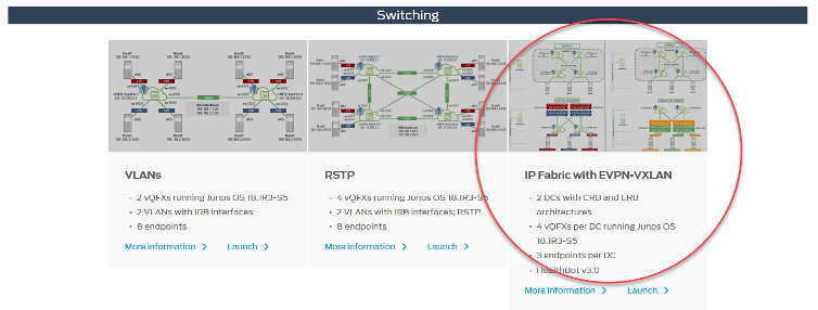
Simply register for an account, log in, check out the IP Fabric with EVPN-VXLAN topology details page and you are on your way. You’ll be in a protected environment, so feel free to explore and mess around with the setup. In fact, you’ll need to – the topology starts up using the edge-routed bridging architecture (the right-side diagram shown above), but you’ll find instructions to reconfigure it to a centrally-routed bridging architecture. Worried you’ll break it? Don’t be. You can tear down your work and start a new session any time.
What is a Centrally-Routed Bridging Architecture?
As discussed in a recent blog, the bridged overlay model does not provide a mechanism for inter-VXLAN routing functionality within the fabric. Depending on your requirements, this may be sufficient – or even desired. However, if you want routing to happen within the fabric you need to consider another option.
The centrally-routed bridging (CRB) model is an example of an architecture that brings routing into the fabric. Also known as a spine-routed overlay, with the CRB model the ‘intelligence’ is at the spine layer, as inter-VXLAN routing is performed by the spine devices.
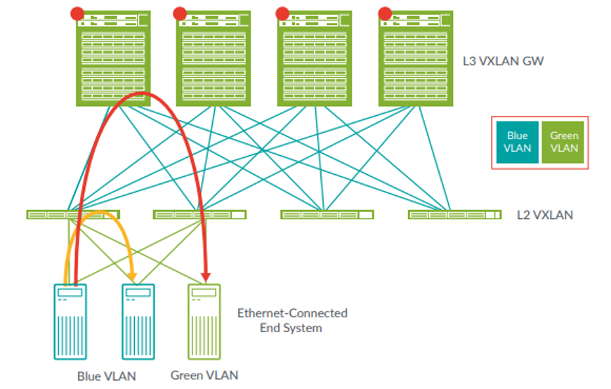
With the CRB approach, bridging generally happens at the leaf layer while routing happens at the spine layer. In the diagram above, traffic flowing between servers in the blue VLAN and attached to the same leaf device can be locally switched at the leaf layer. Traffic between the blue VLAN and green VLAN must be routed, which is done at the spine layer.
This approach generally scales very well across the fabric, though it’s worth noting it can create suboptimal traffic flow for end hosts connected to the same leaf device, as traffic flows up through the leaf device for routing at the spine layer, only to return back down through the same leaf device.
Why a Centrally-Routed Bridging Architecture?
First and foremost, the CRB model is a good option when you want inter-VXLAN routing to happen within the fabric. As far as in-fabric options go, the CRB approach has the advantage of centralizing and consolidating the routing function (vs. distributing it at the leaf layer).
The CRB model can be a good migration option. In legacy architectures, switching is typically performed at lower layers and routing at the upper layer. The CRB architecture is a good fit here since routing is maintained at the upper (spine) layer of the fabric.
Another case for using the CRB approach is when leaf devices don’t support inter-VXLAN routing. Some older switches use ASICs that support only intra-VXLAN switching. In this case, the legacy switches work well as leaf-layer devices with more fully-featured spine layer devices handling the inter-VXLAN routing.
The CRB model is also somewhat easier to configure (vs. the edge-routed bridging architecture), so a good option if you are new to EVPN-VXLAN and don’t have a fabric manager or orchestration tool.
Overall, with routed traffic traveling up through the spine devices the CRB architecture is optimized for DCs running mostly north-south traffic.
Implementing a Centrally-Routed Bridging Overlay
With any EVPN-VXLAN architecture, you must configure some common elements (we described this in a previous blog, Getting Started with Modern Data Center Fabrics), including:
- BGP-based IP fabric as the underlay
- EVPN as the overlay control plane
- VXLAN as the overlay data plane
With a CRB overlay, each layer also requires some specific configuration elements, including:
- Enabling VXLAN and supporting parameters on all devices
- On the spine devices, adding IRB interfaces and inter-VXLAN routing instances
- Mapping VLAN IDs to VXLAN IDs on all devices
- On the leaf devices, assigning VLANs to the interfaces connecting to endpoints
With that, we’ve covered the basics for using a CRB overlay architecture. There are plenty of other details to consider, but this will get you started. We’ll discuss other architectures in a future blog. In the meantime…
Keep Going
To learn more, we have a range of resources available.
Read it – Whitepapers and Tech Docs:
Learn it – Take a training class:
- Juniper Networks Design – Data Center (JND-DC)
- Data Center Fabric with EVPN and VXLAN (ADCX)
- All-access Training Pass
Try it – Get Hands-on with Juniper vLabs


