There’s no question that the go-to in modern data center designs is now a common architecture of an IP fabric to provide base connectivity, overlaid with EVPN-VXLAN to provide end-to-end networking. IP fabrics are a recognition that the global Internet itself represents the most scalable and resilient communications infrastructure the world has ever known. This blog introduces the solution.
Quick Start – Get Hands On
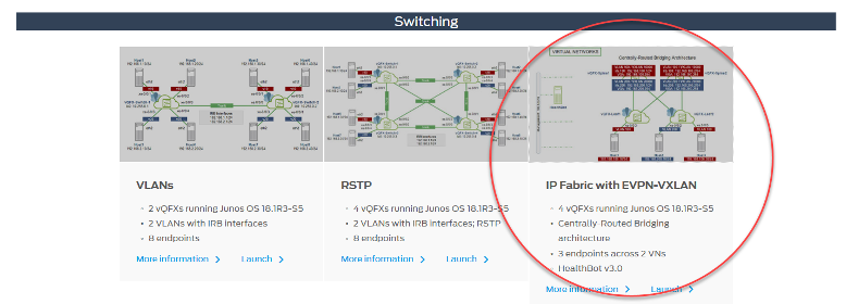
For those who prefer to “try first, read later,” head to Juniper vLabs, a (free!) web-based lab environment that you can access any time to try Juniper products and features in a sandbox type environment. Among its many offerings is an IP Fabric with EVPN-VXLAN topology. The fabric is built using vQFX virtual switching devices and the sandbox includes HealthBot, Juniper’s network health and diagnostic platform.
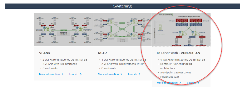
If you’re new to vLabs, simply create an account, login, check out the IP Fabric with EVPN-VXLAN topology details page and you will be on your way. You’ll be in a protected environment, so feel free to explore and mess around with the setup. Worried you’ll break it? Don’t be. You can tear down your work and start a new session at any time.
Why Fabrics for Data Center Networks?
At Juniper Networks, simple explanations are our preference. Let’s start with the background on how we got here. Traditionally, data centers have used Layer 2 technologies such as xSTP and MC-LAG. As DCs evolve and expand, they tend to outgrow their limits; xSTP blocks ports, which locks out needed bandwidth, while MC-LAG may not provide enough redundancy. Furthermore, a device outage is a significant event and larger modular-chassis devices use a lot of power.
It’s safe to say that a new data center architecture is needed. The best way to implement this change is to rearchitect the DC network as two layers: the existing network becomes the ‘underlay’, providing interconnectivity between physical devices and a new logical ‘overlay’ network provides the original endpoint-to-endpoint connectivity. Using an IP-based underlay coupled with an EVPN-VXLAN overlay provides expanded scale and enhanced capabilities not possible with the traditional architectures.
The move to this architecture is with good reason. An ideal DC network provides high interconnectivity and low latency. The modern solution to achieve this uses two levels: spine and leaf, also known as a Clos network. In this model, each leaf device is connected to each spine device as shown below.

A key benefit of a Clos-based fabric is natural resiliency. High availability mechanisms, such as MC-LAGs or Virtual Chassis, are not required as the IP fabric uses multiple links between levels; resiliency and redundancy are provided by the physical network infrastructure itself. You also get full ECMP from this approach, as all links are active.
It’s also worth noting this architectural model is easy to repair. If a device fails, just swap it out; traffic still flows using the other links. Expanding the network is simple – just add a new leaf device alongside the existing ones, cable it to each spine device and you’re up and running.
Evolving your network to this model introduces a new architecture, protocols and monitoring requirements. Overall, it can be a daunting prospect. But not to worry – let’s shed some light on the building blocks of this modern DC fabric architecture.
IP Fabric as Underlay
In DC environments, the role of the underlay network is simple: to provide reachability for the entire network. Note that the underlay doesn’t actually have network ‘intelligence’, that is, the underlay doesn’t keep track of the endpoints or define the end-to-end networking, it simply provides the ability for all devices in the network to reach each other.
Of course, providing reachability requires a routing protocol. The global Internet uses IP with routing protocols like BGP to achieve this and IP fabrics do the same. While BGP is a powerful protocol with loads of advanced capabilities and features, the typical DC fabric underlay uses just a few basic EBGP elements:
- Assign each device its own identifier (AS number)
- Set up peering between spine and leaf devices (as shown below)
- Add a basic routing policy to share loopback addresses information
- Enable load balancing
And that’s it. Do this on each device in the fabric and you will end up with an underlay like this:
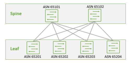
As you can see, building an IP fabric is very straightforward and it serves as a strong foundation for what comes next.
EVPN as Overlay Control Plane
Using a logical overlay in the data center provides several benefits:
- It decouples physical hardware from the network map, which is a key requirement to support virtualization.
- This decoupling allows the data center network to be programmatically provisioned.
- It enables both Layer 2 and Layer 3 transport between VMs and bare-metal servers.
- It has a much larger scale than traditional VLANs.
Like any data network, an overlay consists of a control plane (to share endpoint reachability information) and a data plane (to forward traffic between those endpoints). The overlay control plane provides the network mapping intelligence. This is where EVPN comes in.
EVPN is a standards-based protocol that can carry both Layer 2 MAC and Layer 3 IP information simultaneously to optimize routing and switching decisions. This control plane technology uses Multiprotocol BGP (MP-BGP) for MAC and IP address endpoint distribution, which has the positive effect of minimizing flooding.
In overlay environments, routing information about endpoints is typically aggregated in top-of-rack switches (for bare-metal endpoints) or server hypervisors (for virtualized workloads). EVPN enables these devices to exchange this endpoint reachability information with each other.
Implementing the overlay is quite straightforward as EVPN is a simple extension to BGP. The architecture runs as a single autonomous system, with MP-IBGP as the routing protocol and the spine devices acting as route reflectors. Just like the underlay, configuring the overlay control plane is very straightforward:
- Assign all devices with a common AS number
- Setup peering between spine devices
- Make the spine devices route reflectors and set up peering between spine and leaf devices, using EVPN signaling
- Enable BGP multipath
And again, that’s it.
VXLAN as Overlay Data Plane
With the overlay control plane in place, it’s now time to get the data moving. The actual network ‘overlay’ is a set of tunnels spread across the network. These tunnels terminate at devices called virtual tunnel endpoints (VTEPs); these are the top-of-rack switches and server hypervisors noted earlier. When endpoint traffic arrives at a VTEP device, it is encapsulated and tunneled to the destination VTEP, which decapsulates the traffic and forwards it along to the destination endpoint.
The VXLAN tunneling protocol is a great fit for this task. It encapsulates Layer 2 Ethernet frames in Layer 3 UDP packets, which enables virtual (logical) Layer 2 subnets or segments that can span the underlay network.
In a VXLAN overlay network, each Layer 2 subnet or segment is uniquely identified by a virtual network identifier (VNI). These virtual networks function much the same as VLANs and a VNI mimics a VLAN ID – endpoints within the same virtual network can communicate directly with each other, while endpoints in different virtual networks must be handled through a Layer 3 gateway.
Now there’s an architectural decision to be made around where to place the Layer 3 gateway, that is, where inter-V(X)LAN routing should be performed. Common current options include the centrally-routed bridging model (routing in the spine layer), which is a good option for DCs with lots of north-south traffic and the edge-routed bridging model (routing in the leaf layer), which is a good option for DCs with lots of east-west traffic.
Either way, configuration is again fairly straightforward:
- Enable VXLAN and supporting parameters on all devices
- Add IRB interfaces and inter-VXLAN routing instances in the spine and/or leaf devices, as per your architecture
- Map VLAN IDs to VXLAN IDs
- On the leaf devices, assign VLANs to the interfaces connecting to endpoints
And once again, that’s it!
Is there more you can do? Sure. But this will get you up and running with a data center fabric.
Keep Going
To learn more, we have a range of resources available.
Read it – Whitepapers and Technical Documentation:
- IP Fabric EVPN-VXLAN Reference Architecture
- Juniper Networks EVPN Implementation for Next-Generation Data Center Architectures
- Data Center EVPN-VXLAN Fabric Architecture Guide
- EVPN-VXLAN User Guide
Learn it – Take a training class:
- Juniper Networks Design – Data Center (JND-DC)
- Data Center Fabric with EVPN and VXLAN (ADCX)
- All-access Training Pass
Try it – Get hands-on with Juniper vLabs.
