Telcos are rapidly moving to the telco cloud paradigm for the benefits it brings, including increased network agility, scalability, flexibility and lower latency. Unlike traditional networks where network functionality is implemented by installing static hardware platforms that remain in place for their entire lifespan, in the telco cloud, network functions are virtualized and run as software. These virtualized network functions run on virtual machines (VMs) and containers, which reside on servers in any data center (DC), including centralized DCs and outlying edge cloud sites. This gives network operators greater flexibility in the deployment of network function resources across their networks, as resources can be easily ported from one VM or container to another, from one server to another and even from one data center to another.
The control and management of these network functions can be quite complex and is well handled by Juniper’s Contrail Controller. Contrail Controller manages virtual overlay networks that interconnect groups of containers and VMs, making it easier to manage these resources across multiple DC domains.
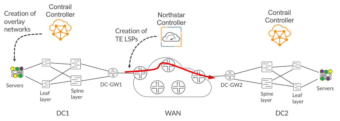
This is illustrated in Figure 1, where Contrail has created three virtual networks (green, purple and yellow) that span two DCs. These virtual networks are separate from each other and, unless explicitly permitted by Contrail, are prohibited from exchanging traffic with each other. While Contrail manages overlay networking, Juniper’s NorthStar Controller creates Segment Routing Traffic Engineered (TE) LSPs or RSVP TE LSPs across the Wide Area Network (WAN). NorthStar automatically optimizes the LSPs in a dynamic fashion. For example, NorthStar is constantly monitoring the network for changes in traffic patterns and latency using streaming telemetry. If latency conditions in the network change to an extent that will impact service performance, NorthStar automatically reroutes the affected low-latency LSPs to lower-latency paths. Similarly, if NorthStar detects congestion on a link, it automatically reroutes some of the LSPs traversing the link in order to ease the congestion.
Achieving Differentiated Transport
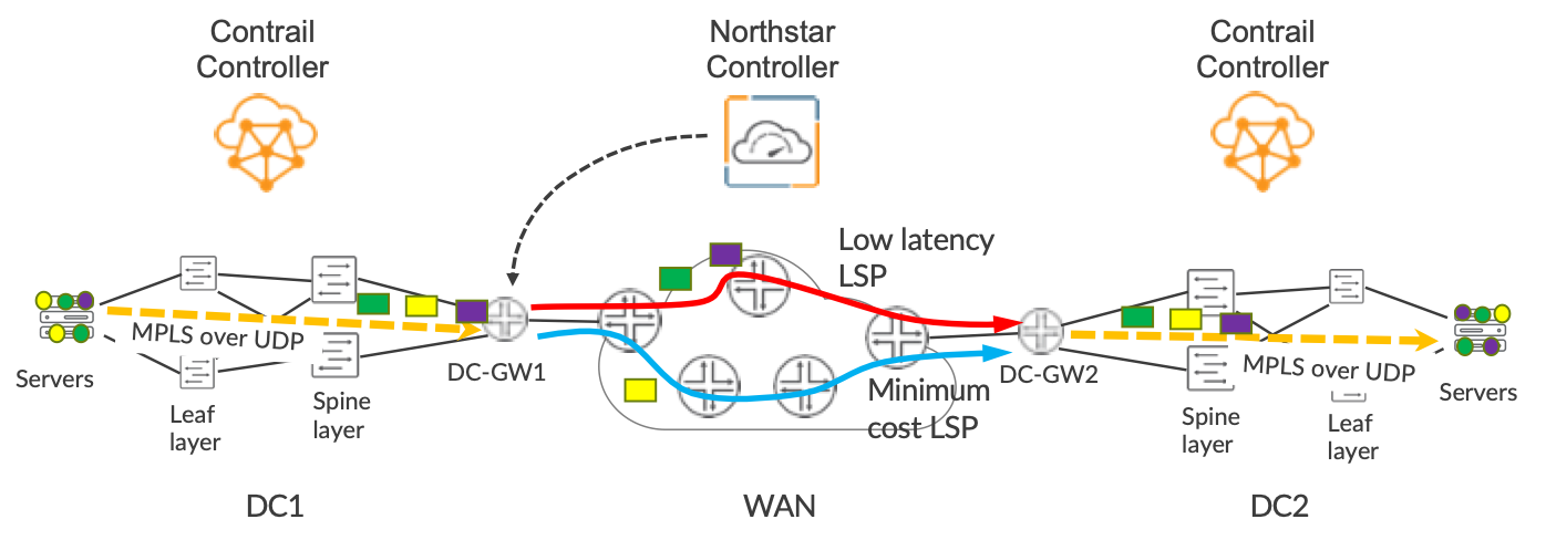
In this blog, we discuss our solution to a critical problem: how do we ensure that traffic belonging to a particular virtual overlay network receives the appropriate transport treatment when traveling across the WAN? For example, in Figure 2, by the nature of their workloads, the green and purple virtual networks need low-latency transport, while the yellow virtual network needs lowest monetary cost transport. We achieve this differentiated transport in a very simple and elegant way because Contrail uses BGP to advertise the existence of VMs and containers that reside in the overlay.
Contrail chooses what flavor of TE LSP is used by a given virtual network by simply adding the appropriate BGP community to the prefixes that it advertises. This results in traffic being steered into the appropriate flavor of LSP at the ingress node of the LSP. In Figure 2, you can see that the DC Gateway in DC1, DC-GW1, is steering traffic from the green and purple virtual networks into the low-latency LSP and traffic from the yellow virtual network onto the minimum-cost LSP. The various LSP meshes can represent different network slices across the WAN, so the solution provides an easy way of coupling traffic from the overlay into WAN transport in a slice-aware manner. In our solution, the TE LSPs do not need to go across the internal infrastructure of each DC, they only need to extend across the WAN. In Figure 2, the LSPs start and end at the DC Gateways (DC-GW), but do not extend across the spine and leaf within each DC.
Often each DC, including its DC gateways, resides in a separate Autonomous Systems (AS) from the WAN AS and may have multiple AS within it. This is no problem for NorthStar, as it can easily create LSPs that cross AS boundaries. This is achieved by giving it some visibility into each AS via BGP-LS, so that it can see all the routers in the WAN, the DC-GWs and the links that interconnect them.
Within the DC itself, IP forwarding is used. An IP tunnel (e.g. MPLSoUDP, MPLSoGRE or VXLAN) is used to transport packets between the DC-GW and the host.
How It Works
Figure 3 shows DC1 on the left and DC2 on the right, with the WAN in between. For clarity, the spine and leaf switches and the WAN routers are not shown. Below, we focus on the green virtual network. Contrail installs a software-based router called a vRouter on each host in the DC. This is very similar to a PE in an SP network. It has a separate VRF for each virtual overlay network and the VMs or containers are analogous to CE devices. As you can see, VM1 in DC1 and VM2 and VM4 in DC2 are members of the green virtual network. Let’s have a look at how VM2’s IP address is advertised via BGP from right to left across the diagram.
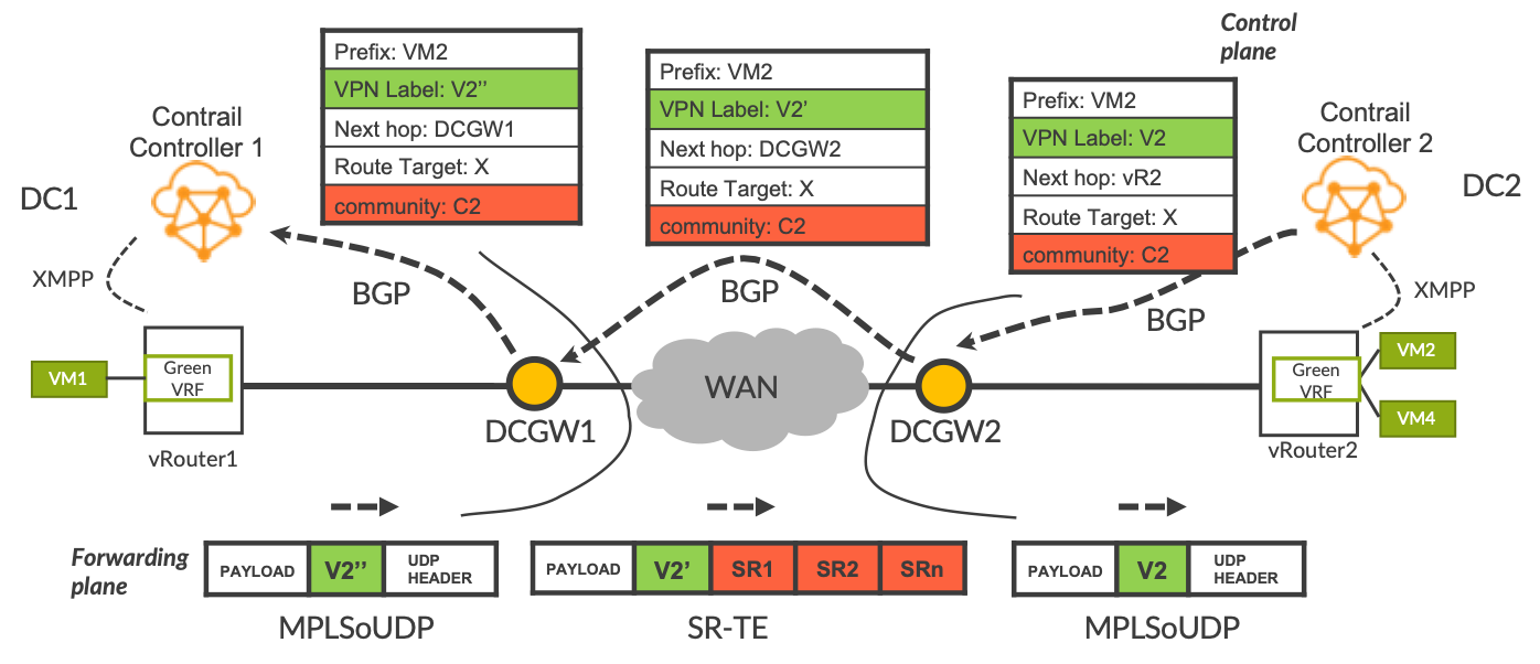
- Contrail Controller 2 advertises VM2’s address via BGP to DCGW2. The advertisement is a typical L3VPN advertisement. It contains a Route Distinguisher, a Router Target and a VPN label (V2). The community C2 determines what flavor of RSVP-TE or SR-TE LSP will be used to send traffic to prefix VM2. It could be a color community or a regular community.
- DCGW2 advertises the prefix to DCGW1 and sets the BGP next-hop to self. As per usual, this triggers a change in the VPN label value to V2’ in the example.
- DCGW1 advertises the prefix to Contrail Controller 1 and sets the BGP next-hop to self. This triggers a change in the VPN label value to V2’’ in the example.
- Contrail Controller 1 advertises the prefix to vRouter1 via the XMPP protocol.
vRouter1 now has the prefix in its green VRF. Let’s now see in the lower part of Figure 3 what happens when VM1 sends a packet addressed to VM2.
- When the packet arrives in the green VRF on vRouter1, vRouter1 sees that the BGP next-hop is the local DC Gateway, DC-GW1.
- vRouter1 puts the VPN label V2’’ onto the packet and puts the packet onto the MPLSoUDP tunnel that terminates at DC-GW1. So, when the packet is in the MPLSoUDP tunnel, the only MPLS label on the packet is the VPN label V2’’.
- The packet arrives at DCGW1. DCGW1 sees the VPN label V2’’ and swaps it for VPN label V2’. The community C2 in the BGP advertisement triggers DCGW1 to select the corresponding TE tunnel to the BGP next-hop, DC-GW2. For example, if community C2 corresponds to low-latency, DCGW1 puts the packet onto the low-latency LSP that terminates at DCGW2.
- The packet arrives at DCGW2. DCGW2 sees the VPN label V2’ and swaps it for VPN label V2. Because the BGP next-hop is vRouter2, DCGW2 puts the packet onto the MPLSoUDP tunnel that terminates at vRouter2.
- The packet arrives at vRouter2. vRouter2 strips off the UDP header and seeing VPN label V2, steers the packet into the green VRF. Then the VPN label is stripped off and the packet is sent to VM2.
Advantages of the Solution
- One can use ECMP within the DC, which is typically a key requirement, and take full advantage of the highly symmetrical spine and leaf topology with all-active links throughout.
- Contrail has direct control of what flavor of LSP is used across the WAN, by simply adding the appropriate community to the prefixes that it advertises, even though the LSPs don’t physically touch Contrail or the hosts. As a result, we don’t need to extend TE into the DC, so we can use conventional low-cost switches in the DC.
- Familiar BGP machinery is used end-to-end – on the WAN PEs and in the Cloud Overlay.
- The architecture means that the DC and WAN remain suitably decoupled, as per current practice, rather than having entangled fate. This leads to better reliability and ease of operation. For example, if a link fails within the spine and leaf, normal ECMP self-healing kicks in and that does not affect the paths of TE LSPs across the WAN. Conversely, if a link fails in the WAN, the affected LSPs are automatically rerouted by NorthStar without affecting traffic flows within the DCs. Overall, we have smaller failure domains and a smaller blast radius caused by any failure.
Network Design Alternatives
Several variations of this scenario are possible. After all, it leverages BGP which is very flexible! As described above, the solution involves DC-GWs that exchange overlay routes directly (via route-reflectors if desired) with meshes of TE LSPs running between the DC-GWs across the WAN. The following alternative approaches are useful if the operator prefers a higher degree of separation between WAN and DC:
- Interprovider Option A: This can be run between each DC-GW and the directly attached WAN PE router, but comes with the disadvantage of needing per-VRF configuration on the DC-GW and the WAN PE. In this case, the TE LSPs would have their endpoints on WAN PE routers rather than the DC-GWs.
- Interprovider Option B: In this case, each DC-GW would have an Option B BGP peering with the directly attached WAN PE router, to exchange the overlay routes via BGP. In turn, the WAN PE routers exchange such prefixes between themselves (via route-reflectors if desired). In such a case, the TE LSPs would have their endpoints on WAN PE routers, rather than the DC-GWs.
- BGP Classful Transport (BGP-CT) Peering can be run between each DC-GW and the directly attached WAN PE router. In this way, the DC-GWs receive colored labelled-BGP routes – one color according to minimum latency, another corresponding to minimum metric. The DC-GW chooses the appropriate color according to the community attached to the overlay route by Contrail. In such a case, the TE LSPs would have their endpoints on WAN PE routers, rather than the DC-GWs. Once the packet arrives at the WAN PE, the packet is launched onto the correct flavor of TE LSP, as determined by the color of the BGP label. If the operator is deploying BGP-CT in other parts of the network, for example to provide glue between core and aggregation, it makes sense to also extend it towards the DCs.
In any of the cases described above, Segment Routing Flex-Algo can be used across the WAN, instead of SR TE or RSVP TE LSPs. In that case, you can define one Flex-Algo for minimum monetary cost and another for minimum latency. Just like the TE case, Contrail chooses which prefixes use a given Flex-Algo by using the same BGP community solution described in this blog. The Flex-Algo would be configured on the WAN routers only. This is useful in a situation where the operator does not use traffic-engineering but still wants some degree of differentiated transport across the core.
In any of these scenarios, instead of having a DC Gateway, the BGP peering on the DC side could instead reside on the spine devices, which would be directly connected to the WAN PE.
Although we looked at traffic traveling between DCs in this blog, in some cases traffic could originate at a PE at the outer edge of the network, and from there needs to be sent to a VNF in a DC. That VNF might be the first hop in a service chain that has been created by Contrail. In such a case, the same principles apply. As long as the PE receives the prefixes originated by Contrail tagged with the appropriate community, the PE can launch the traffic onto the corresponding flavor of TE LSP or Flex-Algo.
Our user-friendly solution provides differentiated transport across the WAN for cloud overlay workloads without disrupting the internal infrastructure of the DC. In this way, a given overlay network created by Contrail receives the type of transport treatment that it needs, as created by NorthStar. The solution easily couples traffic from the overlay into WAN transport in a slice-aware manner.
For more information on the components of this solution, please check out their respective web pages:
If you would like to see a live demo, please ask your account team.
